APPENDIX
TECHNOLOGY DESCRIPTIONS
APPENDIX TABLE OF CONTENTS
APPENDIX TABLE OF FIGURES
Introduction
Current Technologies
Emerging Technologies
Research Not Yet Field Tested
Figure 1 - Typical Pump and Treat System
This appendix is comprised of three sections: current technologies, emerging technologies, and research not yet field tested. The Current Technologies section includes those technologies that have been or are currently in widespread use for TCE groundwater remediation. Emerging Technologies include those remedial technologies that are in the process of being field tested for effectiveness, and those that have not quite gained regulatory acceptance yet. The Research Not Yet Field Tested section includes promising laboratory research and those technologies that may have just started their field testing phase of development.
Some readers may wonder why technologies that are still in the lab have been included in a guide to remediation systems. They were included because this document is intended to be a "living document." The reader should explore all applicable technologies, including those in the lab, when a feasibility study is performed at their site.
Pump and treat (P&T) systems have been used for many years as the primary means to remediate TCE in groundwater. In the recent past, they have fallen out of favor in the environmental community. P&T systems work well initially to bring down contaminant concentrations, but then plateau in their effectiveness. Most P&T systems are slated to be operated for 30 years under a state’s RCRA guidance. Even after 30 years of continuous operation, TCE may remain in the groundwater above action levels.
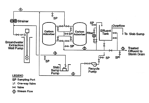
The typical pump and treat system (Figure 1) is designed to bring groundwater contaminated with chemicals, such as TCE, to the surface for treatment via groundwater extraction wells. Once at the surface, there are many treatments available for the contaminants in the water. Common treatments have included air stripping and carbon adsorption.
A typical P&T system will pump groundwater from multiple extraction wells to a central location. Wells are usually placed in the center of the plume to provide for both the greatest contaminant capture and to provide plume control. Plume control may become a driving force in the design of the plume is going off site or shows indications of leaving the installation boundary. Once the contaminated water has been pumped from the ground, it is collected at a central point. The water may be pre-treated to keep from fouling the remediation equipment. Fouling can occur due to suspended solids, iron, or naturally-occurring bacteria.
Once the contaminated water has been pre-treated, it can take many paths for treatment of the TCE. The liquids can be treated via carbon adsorption or run through an air stripper where the off gasses may be remediated via carbon adsorption or catalytic oxidation. The remediated water can be disposed of through the sewer system once it meets regulatory action limits. The carbon adsorption units require periodic replacement to maintain effective remediation.
Figure 1 - Typical Pump and Treat System
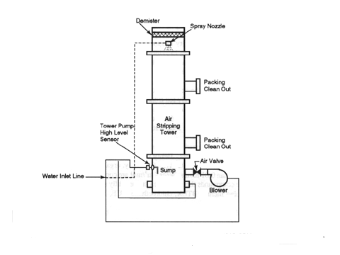
Air stripping is used as a secondary treatment system with groundwater pumping systems to remediate TCE in groundwater. Two of the most common variations are the tower style and the aeration tank air stripper. A typical tower-style air stripper is depicted in Figure 2.
Figure 2 - Air Stripper (packed tower)
Contaminated water is piped to the top of the tower (typical towers are 15 to 40 feet tall). The water is forced through a misting nozzle and down through packing. Newer air strippers have replaced packing with horizontal trays. At the same time the water is falling due to gravity, a blower is forcing air up through the column. The air causes the contaminants to be "stripped" from the falling water. The TCE-contaminated air can be vented to the atmosphere or run through carbon adsorption or catalytic oxidation units for further treatment. The choice is dependent upon state emission requirements and the level of TCE emissions expected. The "clean" water falls to the bottom of the tower where it is pumped out and typically discharged to a sanitary or storm sewer.
There also exists an aeration tank style air stripper that uses air bubbles to strip a tank full of TCE-contaminated water of it TCE contaminants. The height of an aeration style air stripper is typically less than six feet.
Air sparging is a technology that entails bubbling air through TCE-contaminated groundwater in order to volatize the TCE without pumping water out of the ground. Vertical or horizontal wells drilled into the saturated zone are used as a method of delivering the air. Soil vapor extraction systems are typically used in conjunction with this technology to capture TCE and the daughter products that are volatized from the groundwater. Figure 3 shows a typical vertical sparge well installation.
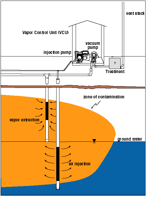
Figure 3 - Typical Air Sparging System
A blower is typically used to push air through an injection well into the groundwater. The air bubbles through the contaminated groundwater and enhances remediation in two ways. First, the bubbling of the air causes the volatile organics to be stripped from the water. Second, the increased oxygen encourages enhanced bioremediation of TCE in the groundwater. Methane or other biological organisms can be injected into the saturated zone to aid bioremediation.
In some cases, vapor extraction wells are used to complement the air sparging system. These wells then extract the TCE (in vapor phase) stripped from the water for treatment. The extraction wells are typically placed in the vadose zone to more effectively capture the TCE that has volatized from the saturated zone.
Carbon adsorption is a popular choice for treatment of aqueous or gaseous phase contaminants. For TCE contamination, treatment of the aqueous phase is not very efficient, therefore, our discussion is limited to treatment of TCE-contaminated off-gasses as part of the treatment train.
Carbon adsorption is a simple technology consisting of hard granules or pellets of carbon arranged in a packed bed or other vessel that adsorbs the TCE contaminants in the air onto the carbon surface. Typically two units are connected in series to provide remediation. When the carbon is manufactured, it is subjected to extremely high temperatures that cause the surface to become porous. Calculations have shown that one cubic foot of granular activated carbon has a surface area of about five square miles (Culligan, 1997).
Ground water must be analyzed prior to implementation of the remedy to see if the water parameters will support efficient adsorption of contaminants. Properties for consideration include pH, hardness, total suspended and dissolved solids, naturally occurring background organics, iron bacteria, and biological growth (Graham, 1995). These parameters are important as it is possible that water with certain biological or bacterial components may foul or clog the porous structure of the carbon, rendering it ineffective for remediation.
The carbon will become saturated with contaminants after some time and lose its effectiveness. At this point, the carbon adsorption units can be removed and regenerated or disposed.
Flameless thermal oxidization (FTO) can also be used in conjunction with groundwater pumping systems to remediate TCE in groundwater. Although listed as a current technology, FTO is relatively new. FTO can be used to treat off-gases from pump and treat systems or soil vapor extraction systems. Treatment provides nearly complete destruction of TCE. Power to a FTO unit can be provided by gas or electric service. The FTO is constructed in a canister as depicted in Figure 4 in which a packed bed is made up of inert ceramic pieces. The ceramic bed is heated to 1600 to 1800 degrees Fahrenheit prior to the injection of TCE-contamination vapors.
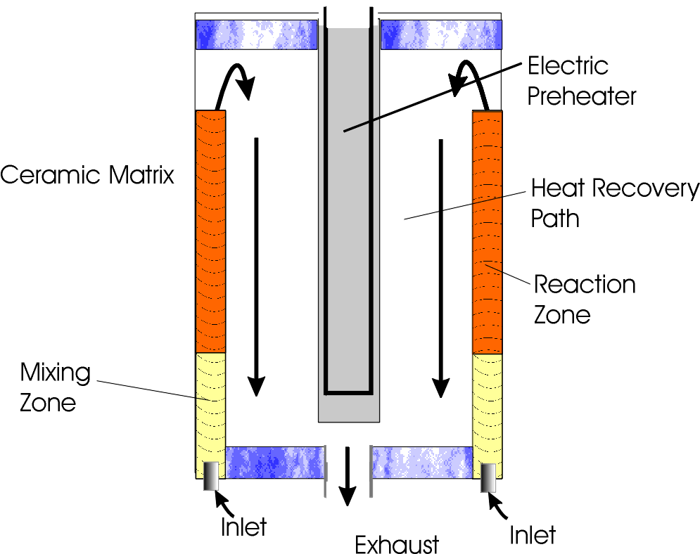
Figure 4 - Typical Flameless Thermal Oxidizer
These extreme temperatures destroy over 99 percent of the TCE. The technology is referred to as flameless because the large ceramic mass that the contaminated air passes through provides flame suppression and a stable temperature in the reactor. After contaminants in the air stream are destroyed, the air stream, containing carbon dioxide, water, and hydrochloric acid, exits the chamber where it may be exhausted into the atmosphere if the hydrochloric acid produced in the system is below action levels. Otherwise, the effluent air stream is run through a caustic scrubber.
Catalytic oxidation is similar to thermal oxidation, but a catalyst is added to accelerate the rate of oxidation. This is accomplished when oxygen and the contaminant adsorb on the catalyst surface where they react to form carbon dioxide, water, and hydrochloric gas (US EPA and USAF, 1994). The catalyst makes it possible to destroy the TCE at lower temperatures than typical oxidation systems. Typical catalysts are made of nickel oxide, copper oxide, manganese oxide, or chromium oxide.
The system works by first preheating the contaminated air to 600 to 700 degrees Fahrenheit. The contaminated, heated air is then passed through a bed of catalysts where the TCE is rapidly oxidized. Off gasses can then be vented into the atmosphere.
More than a do-nothing approach, natural attenuation is gaining momentum as an alternative to consider in remediation of TCE in groundwater. Although natural attenuation has been occurring at many of the sites for decades, it is considered an emerging technology because it is just now being recognized by the regulatory agencies as a valid remedial alternative. The greatest advance has been in the ability to model natural attenuation and the body of knowledge related to the natural attenuation parameters, like dissolved oxygen, that must be understood to model such efforts.
Natural attenuation relies on concepts such as dilution, volatilization, biodegradation, adsorption and other chemical reactions to reduce levels of TCE to regulatory acceptable levels. TCE undergoing natural attenuation usually does so via reductive dechlorination so long as electron acceptors are present. The desired outcome is to be able to prove to the regulatory community that a specific site will bioremediate before the plume can reach potential receptors (e.g., groundwater drinking wells, rivers, or lakes).
This technology has limited regulatory concurrence at present. In order to employ natural attenuation, detailed site information is required. In addition to analyses for TCE and its daughter products, analyses for natural attenuation parameters will also be required. These analyses typically include dissolved oxygen, nitrates, iron, sulfates, methane, etc (AFCEE, 1996). This data is then fed into a computerized attenuation model which will assist the environmental professional in determining plume travel in the future with projected future concentrations.
In many cases, source removal must be employed to achieve regulatory approval. For further information on natural attenuation of TCE in groundwater, refer to the proceedings from the Symposium on Natural Attenuation of Chlorinated Organics in Ground Water, September 1996 and the AFCEE Protocol (AFCEE, 1996).
In Situ Air Sparging with Horizontal Wells
This technology utilizes air sparging (as discussed in Current Technologies) in conjunction with soil vapor extraction in a unique horizontal installation that provides for enhanced remediation of TCE in groundwater. Methods developed in the petroleum industry are used to drill and install horizontal wells below and above the contaminated groundwater.
Figure 5 displays a horizontal well placement. Air is injected using a blower into the lower horizontal well, located in the saturated zone. The air bubbles through the TCE-contaminated water as in standard air sparging. In this technology, the horizontal well placed above the contamination, in the vadose zone, is used to steer and capture the off-gasses before they can volatize at the surface. The placement of the horizontal well affords much greater access to contamination plumes. Research has shown that one horizontal well can replace five to fifty vertical wells (DOE, 1995b.
Methane Enhanced Bioremediation for the Destruction of Trichloroethylene Using Horizontal Wells
This technology takes air sparging using horizontal wells one step farther by adding methane to the sparging wells. When the methane enriched air reacts with the TCE, degradation occurs more readily, resulting in carbon dioxide, water, and soluble chlorine. This breakdown occurs due to bacteria in the soil known as methanotrophs. These bacteria can use methane to "eat" contamination. Figure 5 shows an example of the treatment system.
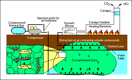
Figure 5 - Methane Enhanced Bioremediation
In a field test at Savannah River Site, M Area, TCE concentrations leveled off to 2 ppb, which is below the MCL of 5 ppb (DOE, 1996b). Methane was consumed at a rate of 50 percent to provide for the TCE destruction. In the field test, catalytic oxidation was used to treat off gases from the vadose zone.
Currently this technology has only been field tested. The advantage of this technology is that a greater amount of TCE is degraded in situ instead of being extracted and treated. This degradation may make the use of a vapor extraction system unnecessary, contingent upon regulatory drivers. Field studies indicate that this technology might be best suited to plumes that are linearly shaped and relatively thin. This technology also works in areas of lower permeability, like in clays.
The reactive wall concept uses a wall of iron filings (iron powder and granular iron have also been used) to reductively dechlorinate TCE. The iron releases electrons necessary to reduce chlorinated compounds when they come in contact with the filings. Laboratory research has also looked into the feasibility of using nickel-plated iron (Appleton, 1996). As the TCE-contaminated water flows through the iron wall, "corrosion" takes places which strips the chlorine atoms from the TCE, breaking it down into ethene and ethane gases (Roush, 1995). The greatest advantage to this technology is that it treats contaminated ground water in-situ. The dechlorinization is complete; there is no transfer of contaminant from one media to another, as in a P&T system. A typical installation is depicted in Figure 6.
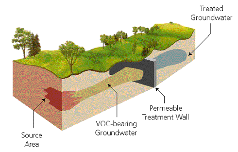
This system has been field tested at Lowry Air Force Base, where a large TCE plume is migrating off base. In this test, the contamination was in shallow groundwater and there was a confining layer approximately 18 feet below ground surface (BGS). Additional field tests are taking place at the Massachusetts Military Reservation.
The construction of a reactive wall at Lowry AFB included the use of sheet piling to create a "funnel" to channel groundwater into the reactive wall. The actual wall was 10 feet in width (Edwards, 1996). The length of the wall (direction of contaminant flow) was approximately 10 feet.
TCE contaminant levels upgradient of the wall were as high as 1,000 ppb before traversing the wall. After traversing the wall, and being dechlorinated, TCE and its daughter products were below analytical quantitation limits.
For a reactive wall to be effective, a general groundwater flow is required in order to get the TCE to move through the system. Groundwater flow at the site must be thoroughly understood. Once the wall is in place, you cannot move it if you determine groundwater flow to be different than first thought. The system is most cost efficient when the contamination is in the shallow groundwater, bounded beneath by an aquitard.
There is additional research being conducted to determine the applicability of this technology in aboveground situations. Field tests have shown that this type of system can replace the use of air stripping and carbon adsorption.
Ultraviolet (UV) Oxidation provides groundwater remediation of TCE that entails complete destruction of contaminants. Hydrogen peroxide and/or ozone are added to the pumped groundwater and then run through a unit that exposes the mixture to UV light. The combination of the chemical additives and the UV light provide for complete destruction of TCE. By products of the process are carbon dioxide, water, and salts.
The system is prone to fouling and thus the groundwater may require pretreatment. The systems cannot handle highly turbid water or water with high metal levels or oil and grease concentrations. This system is not yet widely used for TCE remediation.
There is also a process known as the CAV-OX® process that uses UV oxidation as its baseline technology and adds hydrodynamic cavitation. This enhancement eliminates the quartz tube scaling seen with some other type of UV equipment.
Six phase soil heating is an emerging technology that incorporates high voltage heating with a vapor extraction system. This technology heats the moisture in the soil and helps drive the TCE contaminated water vapor toward an extraction well. Figure 7 depicts a typical site installation.
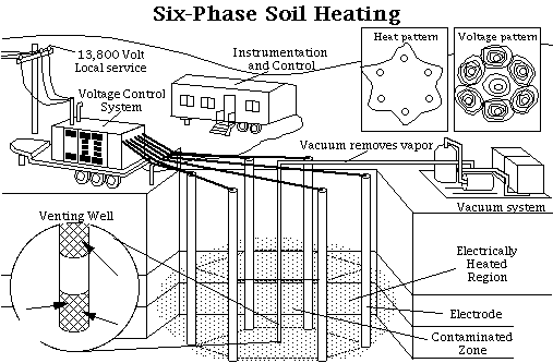
Figure 7 - Six-Phase Soil Heating
The system is put in place by installing six electrodes in a 30 foot circle in the contamination zone. The electrodes extend down to the base of the contamination. Three-phase current is transformed into six-phase current and applied to each of the six electrodes. Although this technology is intended for soil remediation, remediation of groundwater zones is possible by hydraulically lowering the water table (DOE 1995d) to allow local geology to become less saturated. This technology permits permanent elimination of TCE contamination in the treated zone. Therefore, when the groundwater reenters the site, it will not be "re-contaminated" as is possible with traditional pump and treat systems.
As the soil is heated, the TCE will volatize more readily. The soils are typically heated to 100 degrees Celsius in as little as 8 days (DOE 1995d). As the soils are heated and dried, an additional benefit is derived. The air permeability is increased, which further enhances remediation. An extraction well is placed in the middle of the electrode ring, and contaminated off-gases are extracted and treated.
The greatest obstacle to the effectiveness of this technology is the drying of the electrode beds. As the current passes through the soil, the soil tends to dry out. This is especially problematic close to the electrodes. As the soil dries out, the amount of current passing through the soil decreases, thus reducing the effectiveness of the system. In order to counteract this, water must be added to the electrode beds as needed to facilitate effective remediation.
Dynamic Underground Stripping of Volatile Organic Compounds
Dynamic Underground Stripping (DUS) of volatile organic compounds (VOCs) uses steam injection to aid in the remediation of TCE in groundwater. Coupled with steam injection is vapor extraction and direct electrical heating. Field tests indicate that this technology is 60 times more effective than pump and treat to remediate TCE in groundwater (LLNL, 1996).
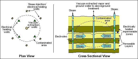
Figure 8 - Dynamic Underground Stripping
The process starts with the installation of injection wells along the outer edges of the contaminant plume. Vapor extraction wells are located near the center of the plume. When steam is injected, it forces the contaminated groundwater towards the extraction wells. Electric heating wells may be used for locations where the soils are not very permeable to vaporize contaminants and drive them into the steam zone.
A beneficial by product of this technology is that the soils behind the steam front are clean and dry.
The LasagnaÔ process is a partnership of DuPont, General Electric, Monsanto, DOE, and EPA. It is a process by which horizontal or vertical fractures are formed in subsurface soils (hydrofracturing)to allow for other remedial actions. The name comes from the layering of treatment zones, similar to layers in lasagna. Electroosmosis is then used to drive the TCE toward treatment zones established via hydrofracturing. Although this technology is not truly a groundwater technology, contaminants in saturated zones (such as is found in clay soils) can be remediated through this technology. Field testing began in late 1994.
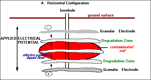
Figure 9 shows a typical horizontal Lasagna configuration. Fractures are established by injecting high pressure air in a borehole sealed off with rubber seals. As the pressure increases, the geologic formation begins to fracture in the horizontal direction. Different products, such as granular iron electrodes, granular carbon, or sand are injected into the fractures, creating zones of high permeability.
Various remedial alternatives can be employed once fractures are in place, using electroosmosis to drive contaminants toward treatment zones. Granular electrodes are placed above and below contaminated zones. Electrical current is then applied, which drives contaminants into the treatment zones. Treatment zones of iron can reductively dechlorinate TCE, while zones of sand or carbon can be used in conjunction with vapor extraction and treatment systems. Using this technique, 98 percent removal of TCE has been demonstrated (RTDF, 1997a). Electroosmosis with methane injection is currently being tested on a TCE plume at Rickenbacker Air National Guard Base in Ohio. At this site, one of the electrodes is made from titanium mesh and the other is granular graphite. A zone of granular activated carbon is located near the bottom of the site to capture TCE contamination as it is drawn down during the electroosmosis cycle. Methane is also injected into a fractured layer at the site in cycles to aid in the bioremediation of TCE.
Phytoremediation is a technology by which plants either take up or facilitate the bioremediation of TCE in groundwater. Remediation can be achieved via four pathways: phytodegradation, enhanced rhizosphere biodegradation, organic pumps, and phytovolatilization (USEPA, 1996a).
Phytodegradation is a process by which plants can break down contaminants like TCE into simpler, less toxic compounds. Plants do this via changes made possible by enzymes.
Enhanced rhizosphere biodegradation is a process that takes place in proximity of the plant roots. The plant exudes sugars, alcohols, and acids from its roots that aid the development of microorganisms that can break down TCE.
Organic pumping refers to a tree’s ability to reach down in to the aquifer and pull up large quantities of groundwater. For example, poplar trees can draw 30 gallons of water per day (USEPA, 1996a). This can also help stabilize TCE in the vadose zone that will otherwise percolate into groundwater.
Finally, phytovolatilization refers to the volatilization of contaminants through transpiration through the leaves on a tree.
Vacuum Vapor Extraction, also known as UVB in the German-introduced variation or in-well vapor stripping, provides in situ air stripping of TCE contaminated ground water. UVB consists of a modified groundwater well that uses air to lift and strip TCE from ground water. The stripped contaminants are extracted in gaseous phase and remediated via ex-situ carbon adsorption. The "cleaned" groundwater is discharged to the vadose zone. This technology never brings groundwater to the surface, thus reducing the components required for remediation. A typical well can be see in Figure 10.
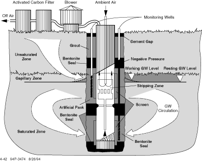
Figure 10 - Vacuum Vapor Extraction
The "cleaned" water will percolate back into the aquifer and then back into the well. The act of percolation helps remove contaminants that may still exist in the vadose zone. This helps to also remediate contamination that may exist in the vadose zone. The zone of influence is a least 40 feet. This system has an inherent advantage in that it can remediate contamination at the base of the aquifer.
Oxygen Enhancement with Hydrogen Peroxide
The addition of hydrogen peroxide to a standard air stripping system can help to speed remediation of TCE in ground water. System configuration is similar to that seen in Figure 3. A hydrogen peroxide delivery system is added to the typical setup and injected into the sparge well. Remediation will occur more quickly that with air sparging alone.
The following technologies are only discussed briefly because of the lack of field data to report. These technologies show promise for the remediation of TCE in groundwater under laboratory conditions. Periodicals and journals should be scanned frequently if these technologies seem appropriate.
Silent Discharge of Plasma Decomposition
This research is being conducted by scientists at Auburn University. The end goal of the research is to develop a technology in which contaminated groundwater is sparged with oxygen and then passed through a silent discharge plasma (SDP). Preliminary research indicated that 99.9 percent of the TCE was destroyed using this technology (Newhouse, 1995). The by products of this technology are carbon dioxide and chlorine.
Fixed-Bed Photocatalysts for Solar Decontamination of Water
This technology harnesses the ultraviolet (UV) portion of the sun’s spectrum to degrade TCE in water when in contact with a titanium dioxide catalyst. This technology has had some preliminary field tests, but is not available for full scale implementation. The greatest advantage of this technology is the almost complete destruction of TCE. The system is also rather simple.
The TCE-contaminated groundwater is pumped over the bed of catalysts and clean water is pumped off the far side of the bed after the catalysis has occurred.